



When separate cooling loops need a dedicated New Energy Vehicle Radiator
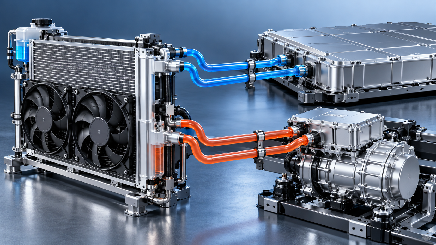
Separate loops are justified when thermal duties and operating windows no longer align
A dedicated cooling loop is warranted when two vehicle subsystems cannot be managed reliably by the same coolant temperature, flow rate, pressure drop, or operating schedule. In a new energy vehicle, that situation commonly appears when the battery pack, traction motor, inverter, onboard charger, DC-DC converter, and cabin-conditioning equipment impose different thermal requirements on one shared circuit.
For project leaders, the decision is rarely about adding a radiator simply because the vehicle has more electrified components. It is about preventing one subsystem from dictating an unsuitable thermal condition for another. A battery may need a tightly controlled coolant range, while an inverter or traction motor can accept higher temperatures and may produce short, sharp heat loads during acceleration, climbing, towing, or repeated charging and discharge cycles. Combining those duties in one loop can make the packaging look simpler at the start, but it may create difficult control compromises later.
A dedicated New Energy Vehicle Radiator should therefore be considered when the thermal architecture needs functional separation, not merely additional heat-rejection capacity. The correct question is: can the existing loop maintain every protected component within its required operating range across the full duty cycle, including high ambient temperature, low vehicle speed, peak load, and heat soak after shutdown? If the answer depends on narrow assumptions, a separate loop deserves serious evaluation.
When one shared circuit becomes a project risk
A shared cooling circuit works best when connected components have compatible temperature targets and when their heat generation rises and falls in roughly the same way. It becomes less attractive when system behavior is uneven. Battery cooling, for example, may be required during charging when the traction system is inactive. Conversely, the motor and power electronics may see their greatest load during vehicle operation, when battery cooling demand is different. A single radiator and coolant path then have to respond to unrelated events.
There are several signs that separate loops should move from a concept-stage option to a design requirement.
- Different allowable coolant temperatures. If one subsystem must be protected at a lower coolant temperature while another can operate at a materially higher level, a common loop may force the high-temperature circuit to run colder than necessary or expose the low-temperature circuit to unwanted heat.
- Independent duty cycles. Charging, stationary auxiliary operation, regenerative braking, sustained climbing, stop-start urban use, and post-run heat soak can create cooling demand at different times. A loop sized around normal driving may not address these events well.
- High consequences of thermal drift. Where temperature variation affects battery performance, power derating, charging behavior, component durability, or diagnostic faults, the cost of inadequate separation is larger than the cost of an extra heat exchanger and associated controls.
- Packaging constraints around the heat source. Long hose runs, repeated branch connections, or poorly balanced coolant paths can make a shared circuit difficult to control. A local or dedicated circuit may reduce the hydraulic penalty and improve response.
- Cooling demand exceeds available airflow at low speed. Many thermal problems are not visible in highway calculations. They emerge during low-speed operation, idling, charging, construction-site movement, delivery routes, or congested traffic, where fan performance and heat exchanger layout carry most of the duty.
These conditions do not automatically require a fully independent radiator for every component group. A low-temperature circuit can sometimes serve both battery and power electronics if their operating limits, contamination risk, and control strategy are compatible. Likewise, a high-temperature loop may combine motor and inverter cooling in some layouts. The engineering point is to group loads that behave compatibly, then isolate the group that does not.
The radiator is part of a loop, not an isolated part number
Teams sometimes identify a heat-rejection deficit and begin by specifying a larger core. That can solve the immediate calculation while leaving the real integration problem untouched. A radiator only performs as intended when coolant flow, fan capacity, air path, shrouding, pump control, hose routing, expansion volume, pressure management, and controller logic support it.
Start with the heat load that must be rejected under the relevant operating condition. This is not simply the sum of component nameplate losses. Project teams need to identify simultaneous loads. Battery conditioning during rapid or repeated charging may overlap with power-electronics cooling. Cabin cooling equipment may share frontal airflow. A vehicle that spends most of its time at modest speed may depend heavily on electric fans, while a machine working under dust, debris, or vibration may lose effective airflow or require more tolerant fin geometry.
Then establish the allowed coolant inlet and outlet temperatures for each loop. The radiator selection follows from the available temperature difference between coolant and ambient air, the intended airflow, and the permissible pressure drop. A compact exchanger can reject substantial heat under favorable airflow, but a calculation based on ideal frontal air velocity is not a reliable vehicle-level answer. Grille restriction, condenser placement, charge-air cooling equipment, protective screens, fan recirculation, and body panels can all reduce useful airflow.
Hydraulic behavior is equally important. A radiator core with excessive coolant-side resistance can reduce flow through sensitive components or force a pump specification that increases electrical load and control complexity. Very low resistance is not automatically ideal either; the system still needs balanced distribution, stable deaeration, and sufficient local flow in each protected branch. The loop should be reviewed as a pressure-flow system, particularly where multiple cold plates, valves, bypasses, and quick connectors are involved.
Use the operating map before selecting core dimensions
Core dimensions are necessary for packaging and comparison, but they do not define thermal performance on their own. Fin density, tube geometry, coolant passages, material thickness, header design, airflow resistance, and fan operating point all influence the result. Two radiators with similar frontal dimensions may behave very differently once installed behind the same grille or stacked with other heat exchangers.
For context, equipment-oriented radiator references such as XD228 RADIATOR FOR CASE & JCB identify a core size of 470*528. That type of dimensional information is useful during envelope planning, fixture design, and preliminary airflow assessment. It should not be treated as a transferable heat-rejection rating for a new energy vehicle loop. The coolant target, thermal load, fan curve, installed air-side restriction, mounting arrangement, and vibration environment remain application-specific.
A practical specification package should therefore state more than overall size. At minimum, it should define the thermal duty point or duty envelope, ambient assumptions, coolant type and concentration, target coolant flow range, maximum permissible pressure drop, pressure requirement, allowable installation envelope, connection geometry, mounting loads, and airflow conditions. The more accurately these inputs represent the vehicle duty cycle, the less likely the project is to discover a radiator shortfall after vehicle integration.
Separate circuits create control work as well as thermal capacity
Adding a dedicated loop gives the controls team more options, but it also introduces more states to manage. Pumps, fans, valves, temperature sensors, pressure behavior, and fault handling should be considered early. A separate radiator may need to operate while the vehicle is parked, during charging, after key-off, or before a traction system reaches normal operating conditions. That changes the electrical architecture and software requirements.
Project leaders should ask how the loop behaves in four conditions: cold start, high-load operation, charging or stationary auxiliary operation, and shutdown heat soak. These states often reveal issues that are missed by a single steady-state thermal calculation.
- During cold start, a dedicated loop may need bypass control so coolant does not reject heat before components reach their intended operating condition.
- Under high load, the controller must prioritize the component with the narrowest protection margin without creating unnecessary fan noise or parasitic power demand.
- During charging, the loop may require cooling availability even when traction cooling is inactive, changing pump and fan command logic.
- After shutdown, residual heat can migrate through a shared circuit. A separated loop can limit that transfer, but only if valves, pump strategy, and sensor placement are designed accordingly.
Sensor position deserves more attention than it often receives. A temperature sensor placed too far from the protected component may report a stable value while a local hot spot develops. Conversely, a sensor placed near a mixing point can react to short fluctuations that do not represent component temperature. The radiator choice and the sensing layout should be reviewed together because changes in flow routing can alter the meaning of the temperature data used by the controller.
Choose separation by failure consequence, not by diagram complexity
A thermal schematic with fewer loops looks easier to manufacture and service. Fewer hoses, valves, fittings, and controls can reduce initial complexity. But the apparent simplicity can be misleading when a single failure mode affects multiple systems. If a shared radiator is partially blocked, an airflow path is restricted, or coolant temperature rises during a demanding event, all connected loads may lose margin at the same time.
Separate loops can contain that exposure. A high-temperature traction loop may continue serving the motor and inverter while a lower-temperature battery loop follows a different control path. This does not eliminate system risk; it distributes it and makes diagnostics more precise. The value is highest where a protected subsystem has a narrow operating window or where an interruption creates operational consequences beyond a temporary power reduction.
At the same time, separation should not be used as a substitute for good heat exchanger packaging. Two poorly ventilated radiators in a crowded front-end module can still perform badly. Stacked arrangements must be assessed for air preheating, fan recirculation, service access, debris accumulation, and cleaning method. In off-road, heavy-duty, or work-vehicle environments, contamination tolerance and maintainability can be as important as peak heat rejection. A fine, dense air-side design may perform well when clean yet lose margin quickly when exposed to dust or debris.
Durability conditions also belong in the specification. Vehicle vibration, mounting stiffness, thermal expansion, coolant chemistry, pressure cycling, and connector loads affect radiator life. A radiator that fits the nominal thermal calculation but lacks suitable mounting isolation or header support can create leakage risk long before its heat-rejection capability is exhausted. The radiator supplier needs the installation environment, not only a drawing and a required core size.
A decision sequence that keeps the project moving
For a project at the architecture or prototype stage, the first decision should be functional: identify which loads can genuinely share a coolant target and which cannot. Next, map simultaneous heat loads against the operating events that matter to the vehicle. Only then should the team allocate radiator capacity and establish airflow requirements.
From there, the work becomes more concrete: define the loop boundary, size the heat exchanger for installed conditions, confirm pump and fan operating points, and verify the control states that occur during driving, charging, and shutdown. Prototype validation should focus on the difficult corners of the operating map rather than only nominal continuous running. Heat soak, low-speed high-load operation, restricted airflow, and changes in ambient conditions often expose the difference between a workable schematic and a robust system.
A dedicated radiator is justified when it gives a protected circuit the temperature control, airflow capacity, and fault isolation that a shared loop cannot provide with reasonable complexity. When the subsystems truly have compatible thermal behavior, keeping them together may remain the better decision. The sound approach is to make that choice from the vehicle duty cycle and system margins, rather than from the assumption that more loops are automatically more advanced.