



What to inspect before accepting a replacement radiator core
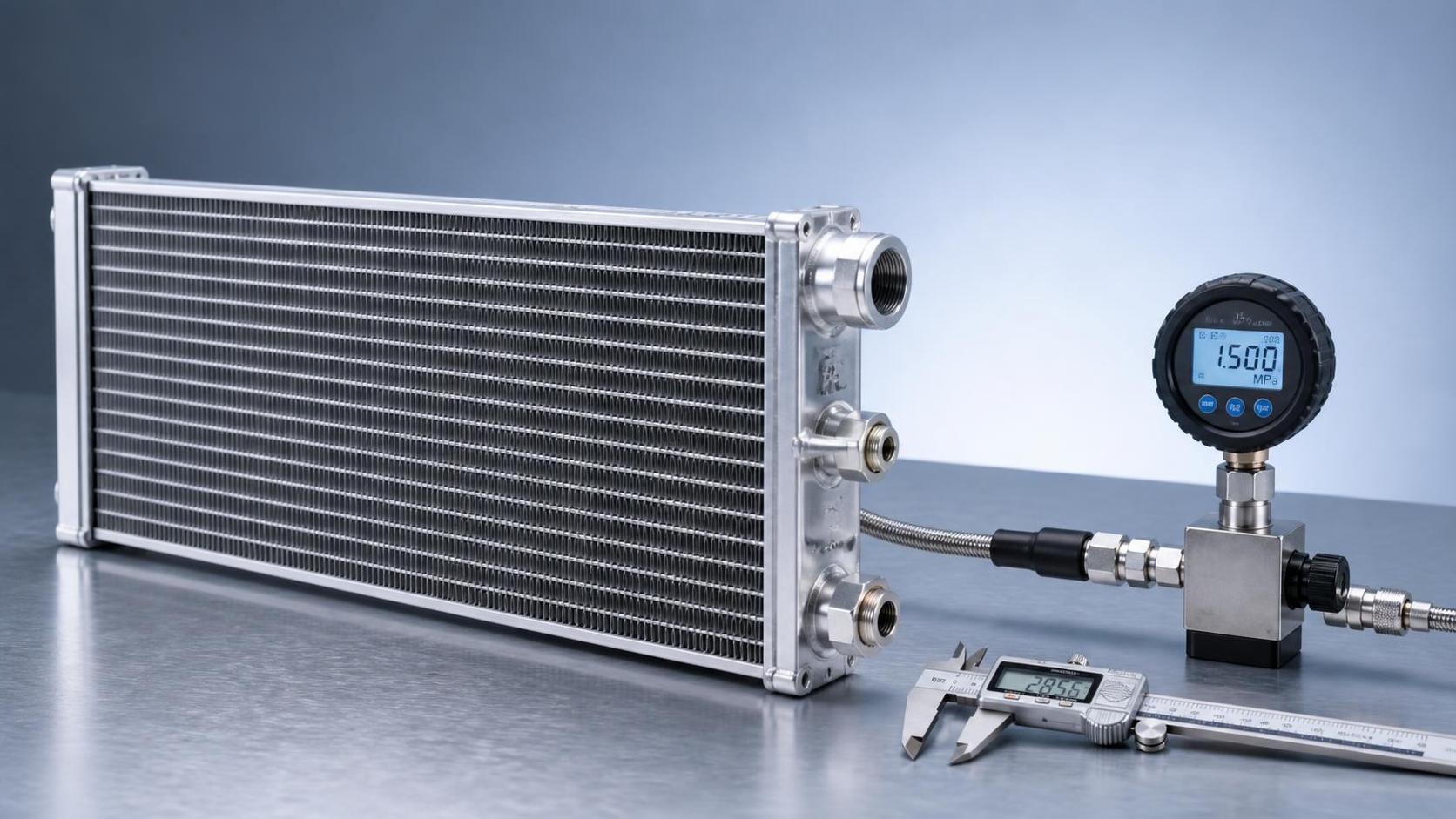
A replacement radiator core can look acceptable on a receiving bench and still fail early in service. The most expensive defects are rarely obvious catalog mismatches. They are the defects that appear after the unit has been installed: a pinhole at a braze joint, restricted coolant flow caused by malformed tubes, fin collapse that reduces air-side heat rejection, or a core that is dimensionally correct but cannot meet the machine’s thermal duty.
For heavy-duty vehicles, agricultural machines, construction equipment, and industrial cooling packs, acceptance should therefore be treated as a controlled verification process rather than a visual sign-off. The objective is not merely to confirm that the radiator core arrived undamaged. It is to establish documented confidence that the core is traceable, structurally sound, pressure-tight, correctly configured, and suitable for the intended cooling system.
There is no single universal “radiator core certification” that substitutes for incoming inspection. ISO 9001 certification may indicate that a supplier operates a quality-management system, but it does not prove that an individual shipment meets a particular vehicle or equipment specification. Acceptance criteria must be tied to the purchase order, approved drawing, sample, applicable OEM requirements, and the operating environment of the equipment.
Start with identity, traceability, and the approved technical baseline
The inspection should begin before unpacking. Compare the delivery documentation, packing list, purchase order, part label, revision status, and lot or batch identification. A radiator core is often only one element of a larger radiator assembly, so confusion between similar cores can occur even where length and width appear close. Differences in thickness, tube pitch, fin density, header configuration, oil-cooler interfaces, mounting details, or coolant inlet and outlet geometry may materially affect performance.
A useful receiving record should link the delivered core to:
- the approved part number and technical drawing revision;
- supplier batch or production date code;
- material declaration or inspection certificate where contractually required;
- pressure-test record, if supplied;
- approved deviation record, if any;
- the purchase order’s stated application and cooling-duty requirement.
Traceability matters most when a field leak develops months after installation. Without a batch reference, the organization may be unable to determine whether the problem is isolated, shipping-related, or associated with a broader production lot. If the supplier has changed a brazing process, tube material, fin stock, flux process, or subcontracted component without formal approval, a complete traceability record becomes the starting point for containment.
For example, a core listed for CASE 100/110 or New Holland TS Platform applications should not be accepted solely because its overall footprint resembles the removed component. In the case of XD82020 RADIATOR FOR CASE 100 110, the stated core size is 506 × 478 × 48 mm and the referenced OEM numbers are 32448 and 73402685. Those identifiers are useful verification points, but the receiver should still compare them with the approved application data, the existing assembly, and any equipment-specific revision notes before release.
Inspect shipping condition before the core is handled or installed
Many apparent manufacturing defects are actually transport or handling defects. Aluminum fins are particularly vulnerable to compression, abrasion, and point loading. A fork contact, an unsecured strap, or poor carton support can deform the core enough to reduce airflow without causing a visible coolant leak.
Document the external condition of the packaging before opening it. Look for water exposure, crushed corners, punctures, broken pallets, missing supports, and evidence that the core has shifted during transit. Photograph damage while the shipment remains in its original packaging. This is important for claims management, but it also prevents an internal handling issue from being incorrectly attributed to the supplier.
After unpacking, inspect the core under adequate lighting. Check both faces and all edges. Particular attention should be given to:
- flattened, torn, or heavily distorted fins;
- areas where fins have separated from tubes;
- bent tubes or local tube flattening;
- damaged header plates, side supports, or mounting interfaces;
- scratches or impact marks around braze joints;
- loose debris, packing material, metal fragments, or residual flux contamination;
- signs of moisture or corrosion, especially on mixed-metal interfaces.
Not every bent fin justifies rejection. Minor fin disturbance can sometimes be corrected using an appropriate fin comb without impairing tube integrity. The acceptance limit, however, should be defined in advance. Broad zones of crushed fins, repeated fin separation, or deformation near tubes and headers should not be treated as cosmetic. These conditions can restrict airflow, create vibration points, and signal that more serious damage may be present beneath the fin field.
Dimensional inspection is a thermal-performance check, not a box-ticking exercise
Core length, width, and thickness are essential, but they are only the beginning. A replacement radiator core may fit into the frame and still deliver less cooling capacity than the original because tube geometry, fin pitch, louver pattern, or effective cooling area differs.
Measurements should be made with calibrated tools and recorded against the approved tolerance. Depending on the design, the inspection plan may include:
- core height, width, and thickness;
- header-to-header distance and tank engagement dimensions;
- tube count, tube spacing, and tube section profile;
- fin pitch or fin density, where this is controlled by the design;
- side-channel position and rigidity;
- mounting-hole locations, bracket offsets, and isolator interfaces;
- inlet, outlet, drain, sensor, and transmission- or hydraulic-cooler connection positions where applicable.
Thickness deserves particular scrutiny. A 48 mm core and a thinner substitute may share the same frontal area but have different coolant volume, tube surface area, and air-side resistance. More thickness is not automatically better either. If the cooling pack has limited fan capacity or a tightly controlled air path, a thicker core may increase air resistance and alter system balance. The correct choice is the core specified for the cooling module, not the one that appears most robust in isolation.
Tube alignment should be assessed across the full core face. Tubes should be parallel and evenly supported by the fin matrix. A visibly bowed tube row, uneven tube spacing, or local compression can indicate handling damage or an uncontrolled manufacturing condition. These defects may reduce coolant flow, produce uneven thermal loading, and increase fatigue stress as the assembly vibrates in service.
Braze quality is one of the most important acceptance risks
Modern aluminum radiator cores commonly depend on controlled brazing to join tubes, fins, headers, and reinforcement members. The joints must remain durable through pressure cycling, thermal cycling, vibration, coolant exposure, and corrosion. A core can pass a simple short-duration leak test while still carrying a braze defect that later develops into a leak.
Visual inspection cannot validate the internal strength of every braze joint, but it can identify warning signs requiring escalation. Examine header-to-tube joints, tube ends, side supports, and any visibly brazed accessories for incomplete fill, excessive voiding, cracking, burn-through, local discoloration inconsistent with the normal process, or irregular braze fillets.
Common concerns include:
- Incomplete brazing: insufficient joining can lead to leakage or tube pull-out under cycling loads.
- Excessive brazing or blockage: excess filler or process residue may partially obstruct coolant passages.
- Thermal distortion: warped headers or uneven joints can indicate uncontrolled heat input.
- Contamination: oil, dirt, flux residue, or trapped foreign material may compromise joint quality or later coolant cleanliness.
Where the risk level, order volume, or failure history justifies it, the incoming plan should include a supplier-approved validation route beyond routine visual checks. This may involve sectioning of sample parts, metallographic examination, burst testing, vibration validation, thermal-cycle testing, or process audits. These are normally periodic qualification controls rather than tests conducted on every received core, because destructive testing makes the inspected part unusable.
Pressure testing must be controlled and meaningful
Pressure integrity is the minimum functional requirement, but the test method must be defined. A statement that a core was “pressure tested” is insufficient unless the test medium, pressure, duration, temperature conditions, and acceptance threshold are understood.
Air-under-water testing can reveal active leaks through visible bubbles, while dry-air pressure decay testing may be used in controlled production environments. Helium-based leak detection provides greater sensitivity but is not always necessary for standard replacement parts. Hydrostatic testing is also used in some circumstances, though it requires careful drying and contamination control before the component enters service.
The appropriate test pressure cannot be assumed from a generic industry number. It should be derived from the approved design requirement, the cooling-system pressure cap rating, OEM documentation, and the supplier’s validated test specification. Testing at too low a pressure may miss defects; testing above the permitted level may damage a core that would otherwise be acceptable. The test equipment itself should have current calibration status, and the result should be linked to the component or lot.
For high-consequence equipment, pressure testing should be considered together with pressure-cycling capability. A static test confirms that the core does not leak at one moment. It does not fully represent repeated pressure changes caused by engine load, thermostat operation, pump pulsation, shutdown heat soak, and ambient temperature variation.
Confirm compatibility with the complete cooling system
A radiator core does not operate independently. Its effectiveness depends on coolant chemistry, flow rate, water-pump performance, thermostat calibration, fan capacity, shrouding, charge-air cooling arrangement, oil-cooler heat rejection, and the cleanliness of the air path. Incoming acceptance should identify incompatibilities before the core is installed into a system that may then be blamed for overheating.
Check whether the core material and joining method are compatible with the specified coolant and corrosion-inhibitor program. Coolant standards and maintenance requirements vary by engine manufacturer and market. Mixing incompatible coolants, using untreated water, or allowing inhibitor depletion can cause corrosion, scale, cavitation-related damage, and blocked passages. A new radiator core cannot compensate for a contaminated system.
Before installation, the receiving team should require confirmation that the system will be flushed where contamination, oil ingress, sealant residue, or corrosion products are present. Reusing degraded hoses, clamps, pressure caps, vibration mounts, or fan shrouds can generate an early failure that is wrongly classified as a core-quality defect.
Fitment verification should also include clearance to fan blades, intercoolers, condensers, guards, and moving components. Mounting points must not preload the core or force it out of alignment. Rigid installation of a component designed to operate on rubber isolators can transfer vibration directly into the header and tube joints.
Use standards correctly: process certification is not product approval
Quality documentation should be assessed for relevance rather than collected as a formality. ISO 9001 may provide evidence of a supplier’s management-system framework. IATF 16949 may be relevant where the supply relationship is within an automotive quality-management context. Neither document, on its own, confirms fitment, heat-rejection capacity, leak performance, or durability of the particular radiator core received.
Likewise, material certificates should be reviewed against the actual contract requirement. They may support traceability of aluminum alloy or brazing materials, but they do not replace functional testing. If the purchase specification cites OEM standards, customer-specific requirements, or agreed test methods, those documents should define the acceptance route. Where requirements are unavailable or ambiguous, the correct response is not to invent a pass/fail threshold; it is to place the shipment on hold pending technical clarification.
For incoming control, the most defensible approach is a documented inspection plan that separates:
- 100% checks: identity, visible transit damage, key fitment features, and required leak-test evidence;
- sampling checks: detailed dimensions, fin condition limits, tube alignment, and workmanship characteristics;
- periodic validation: pressure cycling, thermal cycling, destructive braze assessment, corrosion evaluation, or supplier-process review;
- containment triggers: repeated leaks, batch traceability gaps, undocumented design changes, or recurring thermal-performance complaints.
Release only after nonconformities are clearly dispositioned
Acceptance decisions should not rely on informal judgment such as “close enough” or “probably usable.” Any deviation from the approved specification should be logged with photographs, measurements, batch information, and a clear disposition: accept under written concession, rework under controlled instruction, return to supplier, or hold for engineering evaluation.
Field feedback should feed back into the receiving plan. If returns show leaks at a particular header area, the inspection checklist should focus more closely on that feature. If overheating claims arise despite no leakage, compare the returned cores with approved samples for tube count, fin density, thickness, airflow restriction, and internal blockage. Repeated failures often reveal that the original acceptance plan was checking appearance and dimensions while missing the true failure mechanism.
A replacement radiator core should be released only when it can be identified, inspected, pressure-verified, and shown to match the cooling system it is intended to serve. That discipline reduces avoidable leaks and overheating events, but it also creates a stronger evidence trail when a failure must be investigated across suppliers, installers, and equipment operators.