



How radiator core tube spacing affects coolant flow
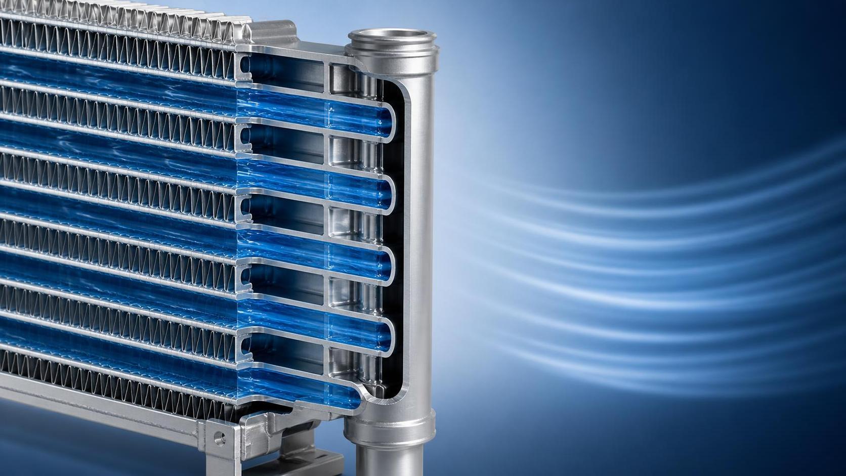
Tube spacing is one of the quieter decisions inside a radiator core, but it has consequences that technical evaluators can see in pressure-drop data, thermal reserve, pump demand, fouling behavior, and durability over the service life of a vehicle or machine. It is tempting to treat a smaller tube pitch as a simple route to more cooling area, or a wider pitch as a simple way to improve coolant flow. Neither shortcut is reliable on its own.
For heavy trucks, construction machinery, and new-energy cooling modules, the relevant question is not whether a given tube spacing is “good.” It is whether the pitch works with the required heat rejection, coolant circuit, available airflow, contamination exposure, package envelope, and manufacturing constraints. A radiator that performs well in a controlled test may become a poor system choice if it imposes excessive pump load, develops uneven flow between tubes, or loses capacity rapidly in dusty service.
Understanding this relationship begins with separating several concepts that are often blended together: tube-to-tube spacing, coolant passage geometry within each tube, fin pitch on the air side, and the total number of coolant tubes. They interact, but they do not influence the cooling system in the same way.
Tube spacing changes the hydraulic network, not just the available surface
In a typical cross-flow or down-flow radiator core, coolant enters a header tank and is distributed across multiple parallel tubes. The spacing between those tubes helps determine how many tubes can be placed within a fixed core height, how the header is configured, and how much heat-transfer surface can be accommodated in the available frontal area.
When tube pitch is reduced, more tubes can usually fit into a given core height. Assuming the tube profile and core width remain similar, this increases the number of parallel coolant paths. More parallel paths can reduce the flow rate through each individual tube, while allowing the system to carry the same total coolant flow. That lower per-tube velocity may reduce friction losses inside the tube, but the overall result depends on the tube’s internal port design, tube length, header losses, and flow distribution.
In other words, close tube spacing does not automatically mean higher coolant-side pressure drop. A core with more tubes may have lower resistance than a less dense core if the additional parallel flow area is substantial. Conversely, a tightly packed arrangement may require header geometry that creates poor entrance conditions or uneven distribution, offsetting the theoretical hydraulic advantage.
For evaluators, the core should be considered as a network rather than as a collection of isolated tubes. The coolant pump sees the combined resistance of the inlet tank, outlet tank, tube entrances, internal passages, bends, hoses, thermostat housing, engine or battery cooling plates, and other circuit components. A radiator design cannot be assessed meaningfully by tube spacing alone.
What happens when pitch is reduced
- More tubes may fit within the same core height, increasing parallel coolant paths and total wetted surface.
- Coolant velocity in each tube may decrease at a given total system flow, potentially changing internal convection and friction characteristics.
- Tube-to-header joints become more numerous, increasing the importance of brazing consistency and header design.
- Available space for air-side fins may be affected, depending on the tube profile and fin configuration.
- Core stiffness, thermal expansion behavior, and vibration response can change with the denser structure.
The apparent benefit of more cooling area therefore needs to be tested against actual flow distribution. If some tubes receive substantially more coolant than others, the effective heat-transfer area is less than the drawing suggests. Uneven distribution can also create localized temperature gradients that increase thermal stress around tube-to-header connections.
Coolant velocity matters, but “faster” is not a universal answer
Coolant-side heat transfer generally improves as turbulence and fluid velocity increase. Higher velocity can thin the thermal boundary layer adjacent to the tube wall and raise the internal convective heat-transfer coefficient. This is why a very low-flow radiator may show disappointing heat rejection even when its nominal core area appears adequate.
But the relationship is not linear and it is not free. Pressure loss rises as flow velocity increases, often sharply once restrictions become significant. The precise relationship depends on coolant properties, operating temperature, passage shape, surface condition, and flow regime. A design that extracts a modest gain in heat transfer by driving much higher coolant velocity can require a larger pump, more parasitic power, or a reduced margin elsewhere in the cooling circuit.
This tradeoff is especially important in systems with variable-speed electric pumps. In a new-energy vehicle or equipment module, excess hydraulic resistance can translate into higher electrical consumption, higher pump noise, and more demanding thermal-control calibration. The radiator may meet a peak thermal target, yet still be inefficient across the duty cycle if the pump must operate at an unnecessarily high speed to overcome the circuit.
For diesel and heavy-duty applications, the issue often appears differently. The mechanical pump may already be selected around engine operating conditions, and radiator restriction must fit within the allowable system pressure drop at rated speed. A change in core layout that alters the distribution of resistance can affect warm-up, thermostat behavior, cavitation margin, or the stability of coolant flow under transient load.
The practical target is sufficient coolant-side velocity to support heat transfer and discourage stagnant regions, without consuming pressure margin that the wider circuit needs. This target should be established from a system-level calculation and then validated by testing, rather than inferred from tube density.
Flow distribution is often the deciding factor
A radiator can have an acceptable total pressure drop while still performing poorly because coolant does not divide evenly across the core. This risk becomes more important as core size increases, as headers become more complex, or as inlet and outlet locations are constrained by vehicle packaging.
At the inlet header, coolant has momentum and may preferentially enter tubes close to the inlet connection. Pressure then falls along the header length, reducing the driving pressure available to tubes farther away. Outlet-side effects can compound the imbalance. The result is a nonuniform mass-flow profile: some tubes carry more coolant than intended, while others contribute less to heat rejection.
Tube spacing influences this indirectly. A tighter pitch can mean more tube entrances over the same header length. That can improve total parallel flow area, but it also changes the interaction between header pressure gradients and individual tube resistance. If each tube has very low resistance, header pressure variation may have a stronger influence on distribution. If tube resistance is too high, the whole core becomes restrictive. Good radiator design balances header losses and tube losses so that flow remains acceptably uniform.
Computational fluid dynamics can help evaluate this behavior before tooling, particularly for large cores, offset inlet arrangements, multi-pass designs, and modules serving multiple cooling loops. However, CFD results remain sensitive to boundary conditions and assumed loss coefficients. Prototype testing should confirm pressure drop and temperature distribution under representative flow rates, temperatures, and coolant mixtures.
Useful validation methods include multi-point temperature measurement, infrared assessment under controlled conditions where applicable, differential-pressure testing, and flow characterization of the complete circuit. A single inlet-to-outlet temperature measurement can conceal a poorly utilized portion of the core.
Thermal performance depends on the air side as much as the coolant side
Radiator tube spacing is sometimes discussed as if it directly controls cooling capacity. In reality, heat must move through several resistances: from coolant to the tube wall, through the tube material, from the tube into the fin structure, and finally from the fins and exposed tube surface to the air. In many automotive and off-highway radiators, air-side resistance is a dominant limitation, especially at low vehicle speed or in hot, contaminated environments.
A denser arrangement of tubes can increase contact between tubes and fins, potentially improving heat conduction into the fin pack. Yet this advantage is conditional. Fin geometry, louver design, fin height, fin pitch, material thickness, air velocity, and blockage all affect the result. If the air passages are too restrictive, fan power demand rises. If fin density is too low, the added tube surface may not be used effectively.
Technical reviews should therefore avoid comparing tube pitch without also reviewing the air-side design point. The relevant test condition should specify at least coolant flow, coolant inlet temperature, air inlet temperature, airflow or fan operating point, and system pressure. A quoted heat-rejection value without these conditions is difficult to compare across suppliers.
Why construction machinery needs a different judgment
For construction machinery, agriculture, mining equipment, and other off-highway applications, the design case is rarely a clean highway-airflow condition. Low travel speed, high ambient temperature, heavy engine load, dust, chaff, mud, and repeated thermal cycling all influence the appropriate radiator core layout.
In these applications, an aggressive fin and tube density can create a capacity advantage when clean, but its service performance may deteriorate quickly if debris blocks air passages. The issue is usually associated most directly with fin geometry, but tube spacing matters because it defines the structure supporting the fin pack and constrains the range of feasible air-side layouts. A core should be judged after considering its likely contamination pattern and cleaning method, not only its initial laboratory performance.
Wider spacing or a less restrictive air-side package may be preferable where equipment must maintain cooling capacity between service intervals. This is not a compromise made because thermal design is less important; it is a recognition that retained airflow under real contamination can outweigh a higher clean-core heat-rejection figure.
Evaluators should also review vibration and mounting loads. A larger, dense core can experience significant fatigue exposure in off-road duty. Tube pitch, tube width, fin bonding, side support, and expansion allowances must work together. A flow-efficient core that develops leaks at repeated thermal or vibration stress is not an acceptable system outcome.
New-energy modules introduce additional constraints
Battery, power electronics, electric-drive, and charging systems commonly operate with narrower allowable temperature bands than conventional engine cooling systems, although the exact limits vary by component and thermal-management strategy. Their coolant circuits may also use smaller electric pumps, multi-loop architectures, chiller connections, or valves that dynamically alter flow paths.
Under these conditions, radiator selection should focus on the full operating map rather than a single maximum-load point. The radiator core must support stable performance at low fan speed, partial flow, and changing ambient conditions, while avoiding excessive hydraulic demand. Tube spacing and passage design may also affect how quickly the system responds to a transient thermal event.
Core dimensions provide a useful packaging reference, but they do not define performance by themselves. For example, the XD81112 RADIATOR FOR NEW RELEASE is identified with an 815*934*40mm core. That envelope may suit a specific installation concept, but its suitability still depends on tube arrangement, internal passage configuration, fin specification, allowable coolant-side pressure drop, airflow through the installed module, and the target duty cycle. Comparing only frontal dimensions or thickness is an incomplete technical assessment.
Common assumptions that should be challenged
“More tubes always mean more cooling.” More tubes can increase potential heat-transfer area, but only if coolant reaches them evenly and airflow can use the associated fin surface. Header losses, fan limitations, and air-side blockage can reduce or eliminate the expected gain.
“A lower pressure drop is always better.” Extremely low restriction can be associated with low coolant velocity or insufficient internal heat transfer, depending on the design. The objective is compliance with the system pressure-drop budget while achieving the required thermal performance.
“Core thickness can compensate for an unsuitable tube pitch.” Increasing thickness adds area, but it also lengthens the air path. In stacked cooling packs, downstream heat exchangers may receive hotter and lower-velocity air. More thickness is not automatically more usable capacity.
“A clean-core test represents field behavior.” It does not adequately represent fouling, variable fan operation, vibration, altitude, transient loading, or degraded coolant condition. Field-representative validation is particularly important for off-highway equipment.
“The same core geometry can serve every coolant circuit.” A core appropriate for a high-flow engine loop may be poorly matched to a lower-flow battery loop, even when both have similar nominal heat loads. Pump characteristics and allowable pressure loss matter.
A practical evaluation sequence
Technical evaluators can reduce uncertainty by starting with system requirements instead of a preferred tube density. Establish the heat load and the conditions under which it must be rejected: maximum ambient temperature, coolant inlet temperature, total coolant flow, available airflow, altitude where relevant, and expected contamination. Then define the acceptable coolant-side and air-side pressure-drop limits.
Next, request information that connects the proposed radiator core to those conditions. At a minimum, this should include core dimensions, tube count and tube profile, tube pitch, fin specification, flow path or pass arrangement, coolant-side pressure drop at stated flow and temperature, and heat-rejection test conditions. Where the application is sensitive, ask how flow distribution was assessed and whether the design has been validated in an installed cooling pack rather than only as a standalone radiator.
Manufacturing controls also deserve attention. For an aluminum brazed core, tube spacing is not merely a drawing dimension; it must be held consistently through assembly and brazing. Dimensional variation can affect fin engagement, braze-joint quality, header alignment, and local stresses. Supplier review should cover process capability, leak testing, cleanliness controls, material traceability, and fatigue validation appropriate to the intended duty. Claims about enterprise qualifications or production scale do not substitute for application-specific verification.
Finally, assess serviceability. Consider what happens when external fins foul, when coolant quality is imperfect, when a pump deviates from nominal flow, or when the machine operates at low speed for extended periods. These conditions reveal whether a promising radiator core design has enough practical margin to serve the actual application.
Tube spacing is best treated as a design lever within a coupled thermal and hydraulic system. The strongest selection decisions come from connecting that lever to measured flow distribution, realistic pressure-drop limits, air-side behavior, and the duty cycle the equipment will actually face. That is where a radiator moves from being dimensionally compatible to being technically fit for purpose.