



What leak tests should an automotive condenser supplier perform
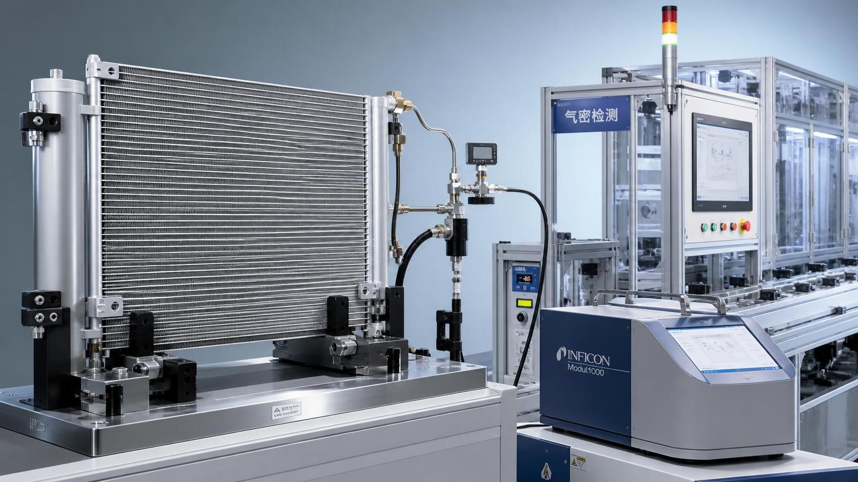
For every automotive condenser supplier, reliable leak testing is essential to protect vehicle safety, cooling performance, and product quality. Quality control and safety teams should verify condenser integrity through pressure decay, helium, bubble immersion, and burst-pressure testing before shipment. The right test plan does more than find obvious holes: it establishes whether the condenser can retain refrigerant through vibration, thermal cycling, corrosion exposure, and years of pressure fluctuations in service.
That distinction matters. A condenser that passes a simple end-of-line air test may still fail after brazed joints fatigue, tube-to-header interfaces distort, or corrosion begins at an unprotected area. For an automotive condenser supplier, leak testing therefore needs to be treated as a layered validation and production-control system, not as a single inspection station.
Start with the actual failure risk, not a generic leak-test specification
An automotive air-conditioning condenser operates on the high-pressure side of the refrigerant circuit. During normal operation, internal pressure changes significantly with ambient temperature, vehicle load, airflow, refrigerant type, and control strategy. Pressure can also rise sharply in abnormal conditions, such as restricted airflow, an inoperative cooling fan, overcharge, or high ambient heat.
Leak-test requirements should reflect the condenser design and its intended vehicle environment. Important variables include:
- Refrigerant and lubricant compatibility, including the pressure-temperature behavior of the specified refrigerant;
- Tube geometry, wall thickness, header construction, and brazed-joint layout;
- Material combination, particularly aluminum grades and connections involving steel fittings or sensors;
- Installation location and exposure to stone impact, road salt, moisture, and vibration;
- Vehicle operating class, such as passenger cars, commercial vehicles, off-road equipment, or electric vehicles with integrated thermal-management systems;
- Customer-specific performance specifications and applicable legal or homologation obligations in the destination market.
There is no universal pressure or leak-rate value that can responsibly be applied to every condenser. Test pressures and acceptance limits must come from the drawing, approved control plan, customer requirement, and engineering risk assessment. A supplier should be cautious when a buyer requests only “100% leak tested” without defining the test medium, stabilization time, reject criterion, traceability method, and calibration requirements.
Pressure-decay testing: the practical foundation of high-volume inspection
Pressure-decay testing is widely used in serial production because it is fast, non-destructive, automatable, and suitable for 100% inspection. The condenser is sealed with purpose-built fixtures, charged with dry filtered air or nitrogen, allowed to stabilize, and monitored for a pressure loss over a defined measurement period.
A properly designed pressure-decay station can detect gross leaks in tubes, headers, brazed seams, fittings, and blocked-off ports. It is especially useful when production volumes make immersion testing impractical. However, the method does not directly measure a leak unless the test system accounts for temperature effects, internal volume, fixture leakage, and material expansion.
The main operational risk is false rejection or false acceptance caused by unstable conditions. Compressed air introduced at a different temperature from the component can cool or warm during stabilization, creating a pressure shift unrelated to leakage. Clamp force variation can create leakage at the test fixture rather than the condenser. A change in condenser internal volume between models can also make one fixed decay threshold misleading.
For reliable pressure-decay control, suppliers should document and verify:
- Dry, clean test gas and controlled supply pressure;
- Fixture sealing design, maintenance intervals, and independent fixture leak checks;
- Minimum stabilization time established through capability studies rather than operator preference;
- Measurement time, charging pressure, allowable pressure loss, and automatic reject logic;
- Temperature-control strategy or compensation method;
- Master parts, known-leak artifacts where appropriate, and periodic system verification;
- Part identification linked to test result, date, station, operator or machine status, and calibration record.
Pressure decay is effective for production screening, but it should not be assumed to identify the precise leak location. When a part fails, a second method is normally required to distinguish a product defect from a fixture or handling issue.
Bubble immersion testing: valuable for localization, limited for final assurance
Bubble testing, commonly called water-bath or immersion testing, remains useful because it makes larger leaks visible and often helps operators identify their source. A pressurized condenser is submerged in water, and the operator checks for a continuous stream of bubbles from a brazed seam, tube, header, manifold, fitting, or damaged area.
Its strengths are simplicity and diagnostic value. It is a sensible process-validation tool after brazing changes, tooling repair, design modification, or an unusual rise in pressure-decay rejects. It can also support failure analysis by showing whether leakage is concentrated in a specific header corner, tube row, weld area, or connector interface.
Its limitations are equally important. Detection depends on water temperature, part orientation, internal pressure, observation time, lighting, bubble size, and operator judgment. Very small leaks may not produce visible bubbles during the available test window. Water can also enter ports or remain in cavities if drying and handling are poorly controlled, increasing corrosion or contamination risk.
For these reasons, immersion testing should generally be treated as a controlled supplementary method rather than the only final release test for a modern automotive condenser. If used in production, the water quality, drying process, minimum dwell time, and visual acceptance standard need to be defined in the control plan.
Helium leak testing: when low leak limits and diagnostic certainty matter
Helium mass-spectrometer testing offers substantially higher sensitivity than ordinary air-based methods and is often the preferred approach for engineering validation, high-value applications, root-cause investigation, and programs with demanding leakage limits. The condenser is either evacuated and exposed to helium externally, or charged with a helium-containing tracer gas while a detector measures escaping helium.
Two broad configurations are common. In a vacuum test, the part is evacuated and helium is sprayed around suspected external locations; helium entering the part is detected by the instrument. In a pressurized tracer-gas arrangement, helium is introduced into the part and the external surface, test chamber, or probe is monitored for leakage. The most suitable configuration depends on cycle-time requirements, target sensitivity, component volume, and the need to locate rather than merely quantify a leak.
Helium testing is not automatically better in every production environment. It requires disciplined control of background helium, clean connections, stable evacuation performance, and trained maintenance personnel. Cross-contamination can create false positives. Poor evacuation, contaminated seals, or inadequate recovery can lengthen cycle times and raise operating cost. The test method should therefore be matched to the leakage risk and customer requirement—not adopted simply because it appears more advanced.
For safety-critical or high-cost programs, helium testing can be particularly valuable in the production-part approval stage. It can establish whether the selected 100% production test has enough margin to catch the smallest economically relevant defect before shipment.
Proof-pressure and burst-pressure tests address a different question
Leak testing asks whether a condenser is currently tight. Pressure-strength testing asks whether it can safely withstand specified internal loads. Both are necessary, but they are not interchangeable.
A proof-pressure test is normally a non-destructive test performed above the expected service-pressure range for a defined hold period. It checks for permanent deformation, visible damage, pressure loss, or other evidence that the assembly cannot maintain structural integrity under the specified proof condition.
A burst-pressure test is destructive. The condenser is pressurized, commonly using a liquid medium because stored energy is lower than with compressed gas, until rupture occurs. The engineering team evaluates burst pressure, failure mode, and failure location. A part that bursts at a high pressure may still be unacceptable if it fails in an unsafe way, such as a fitting separating or a fragment-producing rupture occurring near a service connection.
Burst testing should not be viewed as a routine batch-release test. It is primarily a design-validation and periodic audit tool. Changes to alloy supply, tube wall thickness, braze cycle, header tooling, joint design, or supplier processes may justify renewed structural validation. A strong supplier also trends failure location, rather than recording only the final burst number. Repeated rupture near one header-to-tube transition can reveal a process margin issue long before field returns appear.
Durability testing reveals leaks that a new condenser will not show
Many field leaks do not originate from an obvious manufacturing hole. They emerge after repeated pressure pulses, vibration loading, thermal expansion, corrosion, or a combination of these conditions. That is why validation plans should include pre- and post-test leak checks around durability testing.
Pressure-pulse testing subjects the condenser to repeated high- and low-pressure cycles. It is intended to challenge brazed joints, tube walls, headers, manifolds, and fittings under fatigue conditions. Thermal cycling exposes the assembly to differential expansion and contraction, while vibration testing examines mounting interfaces and tube/header durability under vehicle-like excitation. Corrosion testing evaluates whether protective measures and material choices retain integrity after salt and moisture exposure.
The correct sequence matters. A leak check before durability testing confirms that the sample entered the test intact. A check after each major exposure identifies when leakage developed. If the part is only tested at the end, the supplier may know that it failed but not whether the root cause was pressure fatigue, vibration, corrosion, or handling between tests.
For vehicle programs, test methods are often governed by OEM specifications. Broader documents such as SAE J639, which addresses safety standards for motor vehicle refrigerant systems, may be relevant to system-level requirements, but they do not replace vehicle-maker drawings, regional regulations, or component-specific validation plans. Suppliers should avoid claiming compliance with a standard unless the applicable revision, scope, test conditions, and evidence are confirmed.
The test system itself must be validated
A frequent quality mistake is to validate the product while overlooking the measurement system. A leak station can display stable pass results for days while its fixture seals, pressure transducer, timer, regulator, or software parameters have drifted outside control.
Measurement-system analysis should cover repeatability and reproducibility under realistic manufacturing conditions. This includes different shifts, operators where manual loading is involved, fixture positions, part temperatures, and production rates. Known-good samples alone are insufficient; the system needs challenge parts or calibrated leaks that demonstrate detection capability near the intended reject threshold.
Calibration certificates are necessary but not sufficient. They show that an instrument was checked against a reference at a point in time. Process confidence comes from routine functional verification, locked test recipes, access control for parameter changes, alarm response procedures, and review of trends such as average fill time, stabilization behavior, reject rate, and fixture leakage.
Where quality systems often lose control
Several recurring practices increase warranty exposure:
- Testing only after final assembly: this makes it difficult to isolate whether the defect came from brazing, machining, connector installation, handling, or the test fixture.
- Using one threshold for multiple condenser variants: different internal volumes and geometries may require different test windows and compensation settings.
- Ignoring test-fixture wear: damaged O-rings and misaligned clamps can create artificial rejects or mask sealing issues.
- Allowing rework without traceability: a repaired part needs a defined re-test route and documented disposition, not an informal return to packing.
- Separating leak results from manufacturing data: without links to braze batch, furnace profile, operator, tooling, and material lot, recurring defects remain difficult to contain.
- Equating a pass result with lifetime reliability: end-of-line testing confirms current integrity; durability validation establishes confidence in service life.
These controls are relevant across the heat-exchanger range. For example, a replacement xd81206 radiator for mercedes-benz has a different fluid circuit and duty profile from an A/C condenser, yet it similarly depends on sound brazed joints, pressure capability, fixture integrity, and traceable final inspection. The specific limits must never be transferred from one component family to another without engineering approval.
A defensible release strategy combines methods
In most automotive applications, the strongest approach is not to choose between pressure decay, immersion, helium, and burst testing. It is to assign each method to the question it answers best.
A typical framework uses 100% pressure-decay or tracer-gas testing for shipment release; bubble immersion or helium probing for failure localization; proof and burst pressure tests for design and periodic structural verification; and post-durability leak checks to confirm long-term integrity. The exact plan should be supported by process FMEA, control-plan logic, customer specifications, and evidence that the production test can detect defects of concern.
The final decision criterion is simple but demanding: a condenser should not merely leave the factory without a detectable leak. The supplier must be able to show, with controlled and traceable test evidence, that its leak-test process is capable of preventing leakage-related field risk across the intended vehicle service conditions.