



How a vehicle radiator supplier controls core thickness consistency
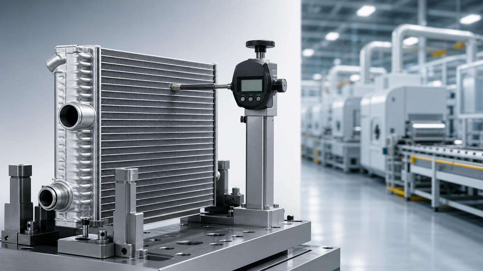
A radiator can look correct on a receiving bench and still create trouble once it reaches assembly. The mounting points may line up, the tanks may be intact, and the part number may match the order. Yet if the core is even slightly thicker or thinner than the intended build, the consequences can appear elsewhere: fan shroud clearance becomes tight, hose routing changes, mounting brackets carry stress, or airflow through a closely packaged cooling stack is altered.
This is a recurring concern in heavy-truck, construction-machinery, and new-energy cooling applications because a radiator core is not a single solid block. It is a formed assembly of tubes, fins, headers, side members, and brazed joints. Its finished thickness is the accumulated result of many dimensions and process conditions. When a vehicle radiator supplier cannot hold that accumulated dimension consistently, a nominally identical part may behave differently from one production batch to another.
The useful question is therefore not simply, “What is the specified core thickness?” It is, “Which conditions keep the actual finished core within its required thickness range after forming, assembly, brazing, cooling, and final inspection?” The answer reveals much more about production discipline than a catalog dimension alone.
Start by defining the dimension correctly
Core thickness is often discussed too casually. In a crossflow or downflow radiator, it generally refers to the front-to-rear distance across the heat-exchange matrix, measured at defined positions between the outer fin surfaces or according to the drawing datums. However, the measurement method must be agreed before any value can be judged.
A measurement taken near the side support can differ from one taken at the center of the core. A reading made on compressed fin edges can differ from one made using controlled contact pressure. If the core face is slightly bowed after brazing, one corner can produce a different result from the opposite corner. These variations do not automatically indicate a defect; they may indicate that the receiving and manufacturing teams are measuring from different references.
A robust drawing or inspection instruction identifies the following points clearly:
- the two surfaces or datums used for measurement;
- the permitted measurement locations across the core face;
- whether the dimension applies before or after brazing;
- the allowable tolerance and any local flatness requirement;
- the measuring tool, contact method, and treatment of compressed fins.
This matters because a core with stable tube-row spacing can still show misleading readings if fins are bent at the edge. Conversely, a visually tidy fin face can conceal an internal stack-height issue. A vehicle radiator supplier should be able to explain how its recorded values relate to the engineering requirement, rather than only stating that a sample “meets drawing.”
Where thickness variation actually begins
Finished thickness is usually influenced long before final inspection. The first source is incoming material geometry. Tube height, fin height, fin pitch, fin stock thickness, header slot position, and side-plate profile all contribute to the assembled stack. In a multi-row core, small variation in each tube layer can accumulate. A process that treats every component as individually acceptable but does not consider stack-up can still produce inconsistent cores.
Tube geometry deserves particular attention. Extruded or welded tubes must maintain controlled height and wall form along their length. A tube that is locally flattened, twisted, or inconsistent at the ends can alter the distance between headers after insertion. For radiator designs using multiple tube rows, variation in row spacing may be more important than the dimensional appearance of any single tube.
Fin material introduces a different risk. Fins are deliberately thin and flexible. Their louver geometry and corrugation height affect not only heat transfer and airflow resistance but also the space they occupy when packed between tubes. If fin pitch drifts, if corrugation height is unstable, or if the fin is stretched during forming, the core can become uneven across its width. Excessive handling pressure can also compress local areas before brazing and make the finished face appear nonuniform.
Headers control the geometry at both ends of the matrix. Their tube slots establish the location of each tube and must agree with the required pitch. Burrs, slot distortion, incomplete insertion, or inconsistent header positioning can shift the entire stack. For this reason, dimensional control at the header is not merely an end-tank concern; it is one of the foundations of core-thickness repeatability.
Forming controls need to match the drawing, not just the machine setting
A common purchasing mistake is to assume that a modern forming machine automatically guarantees stable components. Machines repeat programmed movement, but production consistency depends on tooling wear, coil condition, lubrication, feed alignment, setup verification, and the way formed parts are handled after they leave the machine.
For fins, the supplier should verify actual formed height and pitch rather than relying only on the nominal die setting. Tooling can wear gradually, and material springback can change with incoming coil properties. Sampling at the beginning of a run is helpful, but it does not replace periodic in-process checks, especially on long runs or after a coil change.
For tubes, the key is to inspect geometry in a way that reflects assembly behavior. Width and height readings are useful, but they should be supported by checks for twist, end deformation, and repeatability along the tube length. A tube can meet a simple cross-section measurement at one location while causing inconsistent seating at the header.
Good process control also separates adjustment from correction. If operators repeatedly compensate for a thickness issue by pressing an assembled core into position, the final dimension may temporarily look acceptable while internal stress is being introduced. That stress can later be released during brazing or thermal cycling. The more reliable response is to trace the deviation to the formed tube, fin pack, header, fixture, or setup condition that created it.
The assembly fixture is where individual dimensions become a core
Before brazing, the core is still vulnerable to movement. Tubes, fins, headers, and side members must be held in a controlled relationship while the stack is built. Assembly fixtures should locate the headers and support the core without crushing delicate fin surfaces. Their purpose is not to force an inaccurate stack into a target size; it is to maintain the intended geometry while components are joined.
Fixture condition has a direct effect on repeatability. Worn locating pins, damaged supports, loose clamps, or buildup on contact surfaces can change the position of headers and side plates. These problems may be subtle enough that an operator can still assemble the part, but they can cause thickness drift between shifts or production lots.
During an assessment, it is useful to ask whether first-piece approval includes core thickness before brazing and whether fixture verification is tied to a documented maintenance routine. The answer should address real control points: location surfaces, clamping sequence, compression limits, and the response when a pre-braze core is outside its intended condition.
Pre-braze measurement is especially valuable because it narrows the investigation. If thickness is already inconsistent before furnace entry, the root cause is likely material, forming, or assembly. If pre-braze cores are stable but finished cores vary, attention should turn to thermal processing, support conditions, or post-braze handling.
Brazing can change a well-built stack
In aluminum radiator production, controlled-atmosphere brazing is commonly used to create joints between tubes, fins, headers, and other components. The brazing cycle matters because the core is heated substantially, and different parts of the assembly may expand, soften, and cool at different rates. A stable pre-braze dimension does not guarantee the same finished thickness.
Uneven thermal exposure can lead to distortion, especially in larger cores or designs with different material masses at the headers and side structures. Improper support through the furnace can permit sagging. Excessive clamping can restrict natural thermal movement and leave residual stress. Cooling conditions may also affect flatness and dimensional recovery after exit from the hot zone.
The practical control method is to establish a validated furnace recipe for the specific core family and then protect that recipe from uncontrolled change. This includes loading orientation, fixture design, belt or carrier condition, thermal profile verification, atmosphere management where applicable, and rules for handling the core after brazing. When a new alloy source, tube geometry, or fin design is introduced, the prior recipe should not be assumed to remain suitable without confirmation.
Thickness should be reviewed together with other post-braze indicators. Header alignment, core-face flatness, side-member position, joint appearance, and leak-test results provide context. Looking only at one thickness reading can encourage superficial adjustment. Looking at the dimensional pattern across the core can show whether the issue is localized, directional, or linked to a particular furnace-loading condition.
Inspection should reveal variation, not hide it
A final inspection station can create false confidence when the method is not repeatable. For example, measuring with calipers directly on fragile fin edges may produce different results depending on operator pressure and probe placement. A more suitable approach may use a controlled fixture, defined contact points, depth gauges, or a coordinate-based method appropriate to the drawing requirement. The selected method should avoid damaging the fins while providing sufficient resolution for the tolerance being controlled.
Inspection is stronger when measurements are taken at more than one meaningful location. Center-only checks may miss edge growth, corner distortion, or a tapered core face. The pattern of readings is often more informative than a single average. If one side repeatedly measures thicker, investigators can examine fixture alignment, header seating, furnace support, and material presentation in a focused way.
Measurement-system discipline is equally important. The supplier should understand whether different inspectors obtain comparable readings on the same core and whether the tool remains stable over time. Calibration alone is not enough if the work instruction leaves room for inconsistent placement or force. In technical review, ask to see the method, not just a calibration label.
Use capability evidence in the right context
Process capability information can be useful, but it should not be requested as an isolated number. A capability result only has meaning when the measurement method, sample period, production condition, and applicable tolerance are understood. Results derived from a small trial build or a hand-selected sample do not describe normal serial production behavior.
A credible vehicle radiator supplier can connect dimensional records to traceable production conditions: material lot, forming setup, assembly fixture, brazing run, inspection date, and disposition of any nonconforming parts. This makes it possible to investigate a field or incoming concern without guessing. It also helps distinguish a one-time handling issue from a recurring process shift.
For related charge-air cooling components, the same evaluation logic applies. When reviewing an assembly such as the TRUCK INTERCOOLER FOR VOLVO FH II 420 , core geometry should be considered alongside fitment interfaces and airflow-stack packaging. The component function differs from a coolant radiator, but controlled tube, fin, header, fixture, and brazing relationships remain central to dimensional stability.
A practical way to assess supplier control
When comparing sources, begin with the part drawing and identify the dimension that actually affects vehicle integration. Then ask the supplier to describe its control path from incoming tube and fin material through final inspection. Specific answers are more valuable than broad statements about quality management.
Look for a clear link between the specification, the assembly fixture, the brazing method, and the final measurement record. Ask where measurements are taken, what happens when an in-process reading drifts, and how pre-braze and post-braze data are compared. If the response focuses only on final sorting, the supplier may be detecting variation rather than preventing it.
It is also sensible to review samples under realistic receiving conditions. Check whether the core is measured from the agreed datum, whether fin edges are protected during handling, and whether the packaging prevents compression in transit. A well-controlled factory process can be undermined if finished cores are stacked, strapped, or transported in a way that changes the dimension before installation.
Core thickness consistency is ultimately a process-chain question. Material dimensions establish the starting condition; forming and fixture control establish the assembled geometry; brazing determines whether that geometry survives thermal processing; and disciplined inspection verifies the finished result. When these stages are connected, thickness becomes a controlled characteristic rather than a dimension that is merely checked at the end.