



What fin density should a radiator core have for dusty worksites?
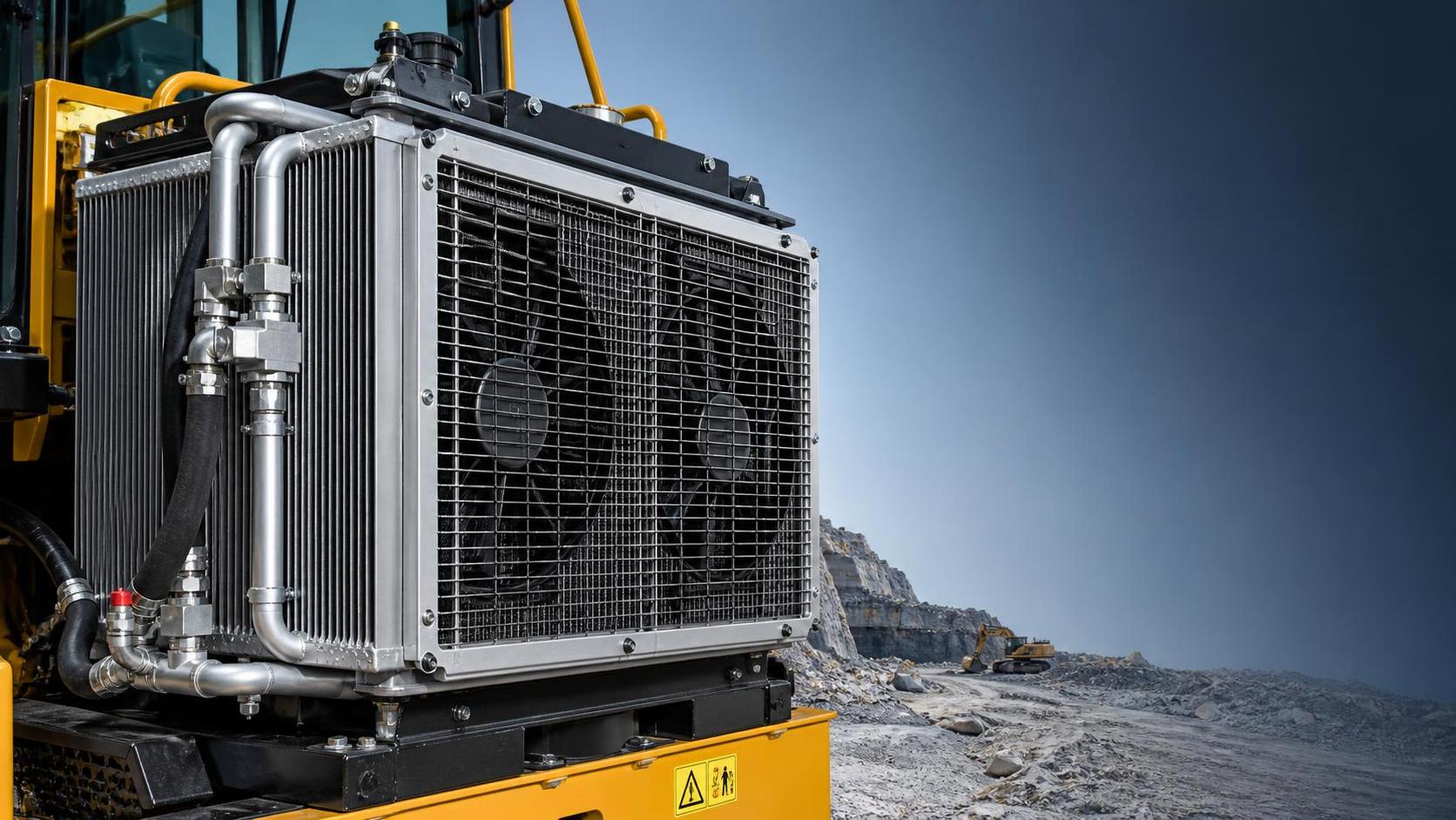
The Question Behind Fin Density
For technical evaluators working with equipment in mines, aggregate yards, demolition sites, farms, ports, and unpaved construction areas, radiator fin density is not a cosmetic specification. It directly affects how long a cooling package can maintain airflow before contamination, how aggressively it must be cleaned, and how much temperature margin remains when the engine is working at its hardest.
The usual question is framed as “How many fins per inch should the radiator core have?” In practice, that question cannot be answered responsibly with one number. A lower-density core generally gives dust, chaff, fibers, and mud more room to pass through or remain on the face before airflow collapses. A higher-density core can provide more heat-transfer surface in clean air, but its smaller passages can load quickly in a dusty duty cycle.
The engineering task is to choose the fin density that protects cooling performance over the actual cleaning interval, not the density that looks strongest in a clean-room comparison. For a machine that sees loose material every day, the best radiator core is often the one that gives up some theoretical compactness in exchange for stable airflow, practical service access, and slower fouling.
Why Dust Changes the Cooling Calculation
Radiator performance depends on more than coolant flow and core frontal area. Air must move through the grille, condenser or charge-air cooler where fitted, radiator, fan shroud, and engine compartment. In dusty environments, the air side becomes the limiting factor sooner than the coolant side.
Fine dust creates a surface layer across the fin pack. Fibrous debris such as straw, wood fragments, paper, insulation fibers, or dry grass can bridge between fins and form a mat. Oily airborne particles create a more persistent layer because ordinary blowing may not remove them. Wet dust is more difficult still: it can harden after heat cycling and partially block passages even when the visible front face appears acceptable.
A high-density fin pack has narrow air channels. This can be useful when the system has limited package space, airflow is relatively clean, and fan capacity is controlled. But in a quarry loader or truck working around powdery material, each narrow channel is more vulnerable to bridging. The cooling package may initially meet a heat-rejection target, then lose usable airflow well before the planned maintenance interval.
That is why a fin-density choice should be evaluated as a contamination-management decision. The relevant question is not just “Can this core cool the engine?” It is “Can it keep cooling the engine after several shifts of the site’s normal dust exposure?”
There Is No Universal Low-FPI Rule
A common field recommendation is simply to specify fewer fins per inch for dusty worksites. The direction is usually sound, but the rule can become misleading when it ignores the rest of the cooling system.
Lower fin density increases the free area available for airflow and tends to make debris removal easier. However, fewer fins also reduce fin surface area. If tube design, core thickness, frontal area, airflow, or coolant-side performance are not adjusted accordingly, the system may lose heat-transfer capacity under high ambient temperature and heavy load.
Conversely, a denser core should not automatically be rejected. It can work in a dusty application if the machine has adequate frontal area, a strong reversible or variable-speed fan strategy, effective pre-cleaning at the intake side, sensible stack spacing, and a cleaning regime that is genuinely followed. The risk rises when a dense core is selected mainly because it fits an existing envelope or because a catalog comparison favors a high fin count without considering contamination.
For most dusty heavy-duty applications, evaluators should treat lower-to-moderate fin density as the starting direction, then validate it against the complete heat-rejection and airflow requirement. The correct result is a balanced core geometry, rather than the lowest possible fin count.
Start With the Duty Cycle, Not the Catalog
Before comparing core drawings, define the conditions that produce the highest thermal risk. Rated engine power alone is insufficient. Two machines with the same engine can require very different radiator specifications because their work patterns, fan operation, and contamination exposure differ.
- Ambient temperature: Identify the expected upper operating range, not only annual average weather. High ambient temperature leaves less margin when the core begins to foul.
- Engine load profile: Continuous high torque at low vehicle speed is particularly demanding because heat generation is high while ram-air contribution is low.
- Vehicle or machine speed: Slow-moving loaders, excavators, drilling rigs, and stationary power equipment rely heavily on fan-generated airflow.
- Dust type and particle behavior: Dry mineral fines, coal dust, cotton-like fibers, grain chaff, and wet clay do not block a core in the same way.
- Stack arrangement: A radiator placed behind an air-conditioning condenser, charge-air cooler, hydraulic cooler, or transmission cooler receives preheated and partially obstructed air.
- Cleaning interval: Specify the longest realistic interval between effective cleaning, including shifts where operators are under production pressure.
- Service access: A core that requires dismantling guards or adjacent heat exchangers to clean properly will often be cleaned poorly or late.
These inputs determine whether fin density is the leading concern or only one of several constraints. In a dry aggregate operation, contamination may dominate the decision. In a high-temperature urban delivery cycle, package space and low-speed fan performance may matter as much as dust loading. In agricultural use, seed fluff and chaff may make face-cleanability more important than a small difference in laboratory heat transfer.
Assess the Whole Air-Side Path
Fin density cannot be selected in isolation because the radiator is normally one element in a cooling stack. The first heat exchanger in the airflow path often captures the largest share of contamination. If a condenser or charge-air cooler is mounted ahead of the radiator, a relatively open radiator core can still overheat because the upstream component is blocked.
Technical reviews should document the airflow path in order: grille opening, protective screen, pre-cleaner where present, front heat exchanger, intermediate gap, radiator, fan, shroud, and outlet path. Each restriction adds pressure loss. When dust builds, the fan must overcome a larger static-pressure requirement to maintain flow. A fan that was adequate with a clean stack may no longer sustain the required flow after partial fouling.
Stack spacing deserves specific attention. Very tight spacing makes the package compact, but it also prevents direct cleaning of internal faces and allows debris to accumulate between exchangers. For severe-duty installations, accessible separation and cleaning direction can matter more than maximizing the number of cooling surfaces in a small package.
Evaluators should also inspect the fan shroud. A poorly matched shroud can cause recirculation, uneven flow across the radiator face, or a dead zone in the corners. In those conditions, changing fin density may address symptoms while the real issue is airflow distribution.
Fin Geometry Matters Beyond Fins Per Inch
“FPI” is useful shorthand, but it is not a complete radiator-core specification. Two cores with a similar fin count can behave differently because fin height, louver design, fin thickness, tube pitch, tube width, core thickness, and material construction all affect air resistance and heat transfer.
Louvered fins, for example, increase turbulence and can improve heat exchange when clean. Yet the same geometry may retain certain fine or fibrous materials more readily than a more open profile. Tube spacing affects how much air passage remains available. A thicker core can add capacity, but it may also increase air-side pressure drop if the flow path is not designed carefully.
This is why procurement documents should avoid specifying only core dimensions and fin count. The supplier should be asked to provide the intended duty condition, pressure-drop behavior, heat-rejection basis, and material details. Where a replacement radiator is being evaluated, compare the entire core construction with the approved configuration rather than accepting a claimed equivalence based on external size alone.
A useful review item is the performance condition behind any cooling claim. Was the core assessed with clean air, a full vehicle stack, representative fan speed, defined coolant temperature, and an ambient condition relevant to the application? If those inputs are unclear, the number cannot be used as a reliable basis for a severe-duty choice.
Choosing a Practical Density Range
Exact fin-density targets are application-specific and should be verified with the equipment manufacturer or a thermal-system supplier. Still, a qualitative selection framework can reduce avoidable mistakes.
This framework should be treated as a decision path, not a specification table. A machine operating intermittently in a mine may tolerate a different design from a continuously loaded machine in the same mine. Similarly, a vehicle equipped with a well-maintained reversible fan may support a denser core than an otherwise similar vehicle cleaned only at the end of the week.
Cleaning Practices Can Reverse the Decision
Cleaning is often assumed to compensate for a restrictive core. In field use, that assumption is unreliable. Compressed air directed from the wrong side can push debris deeper into the fin pack. Excessive pressure or an incorrect nozzle angle can bend fins, reducing airflow permanently. High-pressure water can be effective for certain deposits, but it can also damage fins, force contamination into joints, or leave residues if the procedure is poorly controlled.
The cleaning method must match the contamination type and core construction. Dry loose dust may respond to low-pressure air applied from the fan side outward. Oily or bonded contamination may require an approved cleaning agent and controlled water rinse. Fibrous material may need manual removal at protective screens before it is driven into the cooling stack.
For procurement teams, this has a direct specification consequence: ask how the core is expected to be cleaned and whether every face can be accessed in the installed position. A serviceable, moderately open core may deliver better lifecycle performance than a nominally higher-capacity core that operators cannot clean correctly.
Use Field Evidence Instead of One-Time Temperature Checks
A single successful temperature test after installation is useful but incomplete. The important measurement is thermal behavior as contamination accumulates. Record coolant temperature, charge-air temperature where relevant, fan duty, ambient temperature, engine load, and cleaning events over repeated cycles. The trend is more informative than an isolated reading.
Watch for a gradual rise in fan-on time, more frequent derating, increasing temperature spikes during low-speed load, or a growing difference between pre-cleaning and post-cleaning temperatures. These patterns indicate air-side fouling or insufficient airflow reserve. If cleaning produces only limited recovery, inspect for compacted debris between stack layers, damaged fins, coolant-side restrictions, recirculation, thermostat issues, fan-control faults, and pump performance before concluding that fin density alone is wrong.
Pressure-drop testing can be valuable during development or fleet problem analysis, although it may not be available in routine field service. Where formal test equipment is unavailable, consistent inspection photos, infrared checks used correctly, fan-command data, and logged temperatures can still provide a defensible comparison between alternative core designs.
Replacement-Core Decisions: Do Not Reduce the Review to Size
Replacement programs frequently focus on mounting points, inlet and outlet positions, and external core dimensions. Those are necessary checks, but they do not establish thermal equivalence. A radiator may fit the vehicle and still create overheating risk because the internal tube-and-fin design changes the airflow resistance or heat-transfer balance.
For example, a Nissan application may list a core size of 665 x 634 mm, but the evaluation should continue beyond that envelope. When reviewing a unit such as XD6018 RADIATOR FOR NISSAN, confirm the vehicle configuration, installed cooling stack, tube arrangement, fin geometry, tank and mounting compatibility, pressure requirements, and the operating environment. The stated core size is an important fitment reference; it is not by itself proof of suitability for a dust-intensive duty cycle.
This distinction matters especially for fleets that operate the same nominal vehicle model across different regions. A radiator core appropriate for paved distribution routes may not give the same service interval on a site-haul vehicle that spends much of its time at low speed behind dust-generating equipment.
Supplier Questions That Expose Real Risk
A technically useful supplier discussion should move beyond “What is the FPI?” Ask for the basis of the design recommendation and whether the supplier has considered fouling, air-side pressure drop, and service method. The following questions are practical:
- What duty condition was used to assess heat rejection?
- How does the proposed core differ from the existing design in tube pitch, fin profile, thickness, and air-side restriction?
- Is the recommendation intended for clean-road use, mixed duty, or sustained heavy dust?
- What cleaning direction and method does the supplier recommend?
- Can the design be validated in the full cooling stack rather than as an isolated core?
- What quality controls verify brazed-joint integrity, fin condition, dimensions, and leak resistance? Test methods and acceptance criteria should be confirmed for the specific supply program.
- Is there traceability by batch or production lot for a fleet deployment?
These questions also support lifecycle purchasing decisions. A lower unit price can be offset quickly by more frequent cleaning, lost machine hours, fan-power penalties, recurrent overheating events, or premature replacement caused by damaged fins. Technical procurement should compare total operating impact, especially where equipment availability has a high cost.
The Better Specification Is an Operating Margin
For dusty worksites, the preferred fin density is usually the one that preserves an acceptable cooling margin before the next realistic cleaning event. That typically points toward a more open radiator core than would be selected for a clean, space-constrained on-road application, but it does not justify selecting the lowest density without thermal validation.
The strongest specification links core geometry to the actual duty cycle: worst-case ambient temperature, sustained load, stack arrangement, fan capability, dust type, and service interval. It also requires that performance be reviewed after controlled contamination or representative field exposure, not only when the heat exchanger is clean.
When evaluators make that shift, fin density becomes what it should be: one design lever in a cooling system that must continue working when the worksite is at its least forgiving.