



New Energy Vehicle Radiator sizing for repeated DC fast charging
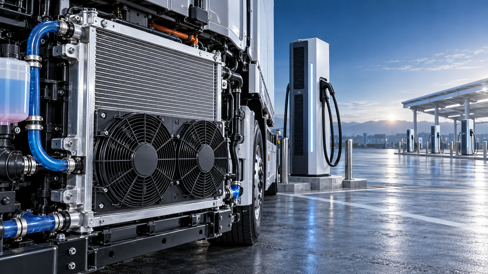
A radiator sized only for the highest expected charging power is often undersized in service. Repeated DC fast charging is a cumulative thermal event: heat enters the coolant loop during each session, airflow may be limited while the vehicle is stationary, and the next charge can begin before the system has returned to a useful thermal baseline. A New Energy Vehicle Radiator should therefore be selected against the full charging duty cycle, not a single peak heat-rejection point.
For a technical evaluation, the practical decision is not simply “how much larger should the core be?” The correct radiator must reject the expected heat while preserving acceptable coolant flow, fan power, package space, service access, and durability through frequent temperature cycling. Increasing frontal area or core thickness can help, but either change can create a different limitation elsewhere in the cooling system.
Start with the charging duty cycle, not the charger rating
A charger’s rated output is not the same as the heat load reaching the vehicle coolant. Battery cells, busbars, contactors, charge cables, onboard controls, DC/DC equipment, and related power electronics all have different loss paths. Some heat is handled by a dedicated battery loop; some may enter a shared low-temperature loop; some is rejected through separate cooling hardware. The radiator calculation must follow the actual loop architecture.
Build the assessment around the most demanding credible use pattern. That normally includes charging power and duration, the interval between sessions, battery state of charge at arrival, vehicle dwell time, ambient temperature, solar loading, and whether the cooling fans can operate at their intended speed while parked. Fleet depots, highway charging stops, port operations, and shuttle routes can produce very different thermal conditions even when vehicles use the same charging equipment.
A single short high-power session may create a high instantaneous load but remain manageable because the coolant and surrounding structure absorb part of the energy. Consecutive sessions are more difficult. If the radiator cannot restore coolant temperature between events, thermal accumulation reduces the margin for the next charge. The control system may then limit charging power, increase fan demand, or impose a longer cool-down period. These outcomes can affect operational throughput even when no component reaches an immediate fault condition.
Define the radiator’s required heat rejection correctly
Radiator sizing begins with a heat balance for the loop, not with a catalog core dimension. The required heat rejection is the heat entering the coolant minus the heat stored temporarily in coolant, battery hardware, pipes, and other loop components. For repeated fast charging, steady-state capacity matters, but transient behavior matters too.
Use the expected coolant inlet temperature to the radiator, the allowable coolant outlet temperature, available ambient air temperature, airflow through the core, and coolant flow rate as connected inputs. A radiator can only transfer heat when there is a useful temperature difference between coolant and air. On a hot day, that difference shrinks. At a stationary charger, vehicle-speed airflow disappears and the fan, shroud, grille path, and obstruction from adjacent heat exchangers become dominant.
The target should not be the lowest possible coolant temperature. It should be a stable operating range that supports battery and power-electronics controls without excessive fan energy, noise, or pressure drop. Selecting for an unrealistically low outlet temperature can lead to an oversized core, difficult packaging, high fan power, or performance that cannot be realized in the installed vehicle.
Three thermal conditions should be evaluated separately
The third condition is frequently the decisive one. A radiator that performs well with simulated road airflow may struggle at a charger if hot discharge air recirculates toward the front face of the core or if another heat exchanger preheats the incoming air.
Air-side performance often decides the result
Core area is visible and easy to compare, but it is not a complete performance measure. Fin density, tube geometry, core depth, louver design, fan shroud coverage, grille restriction, and the installed heat-exchanger stack all change air-side resistance and heat transfer. A dense core can increase surface area, yet it may also require more fan static pressure. If the chosen fan cannot overcome that resistance, the expected gain may not appear in the vehicle.
Assess the radiator as part of an air system. Confirm the effective inlet opening, duct seals, bypass paths around the core, fan-to-shroud clearance, and discharge-air route. A gap that allows air to bypass the core can have a larger effect than a modest change in fin specification. Likewise, placing a battery chiller, condenser, charge-air cooler, or auxiliary cooler in the same airflow path requires an order-of-stack review. The downstream heat exchanger sees warmer air and cannot be assessed using ambient temperature alone.
For stationary fast charging, fan control needs attention beyond maximum speed. A control strategy that waits too long before increasing fan output can allow a temperature rise that is difficult to recover during the session. Continuous maximum fan operation is not automatically better either; it raises electrical demand and noise while potentially delivering little additional flow once the system reaches another restriction. The fan curve should be matched to the installed radiator-and-stack pressure drop.
Do not trade thermal capacity for excessive coolant restriction
On the coolant side, more tubes, longer flow paths, smaller passages, or compact headers may raise heat-transfer potential, but they can also increase pressure drop. In a shared loop, added restriction can reduce flow through the battery cold plate, inverter, charger interface, or other critical branches. The pump may compensate only by consuming more electrical power, and its operating point may move outside the efficient region.
Evaluate the radiator pressure drop at the actual coolant flow and fluid condition, rather than at a nominal catalog point. Flow can vary with pump command, coolant temperature, glycol concentration, branch-valve positions, and system aging. Check the full loop curve: radiator, hoses, quick connectors, cold plates, valves, filters, and any de-aeration hardware all contribute.
Coolant distribution inside the core also matters. A large core with uneven header distribution can leave parts of the surface underused. This becomes more relevant when packaging forces unusual port locations, inclined installation, or complex hose routing. The chosen design should support reliable filling and purging, avoid local high points that trap air, and retain adequate expansion volume for repeated temperature swings.
Packaging decisions that affect durability
Repeated DC fast charging creates frequent thermal expansion and contraction. The radiator is not exposed only to heat; it sees vibration, pressure pulsation, mounting loads, and movement from connected hoses. A technically adequate core can still have a short service life when installed in a rigid or poorly supported assembly.
Review mounting isolation, tank-to-core joint design, hose loads, fan-module attachment, and clearance to surrounding hardware. The core should not become a structural member for a heavy shroud, charging assembly, or adjacent heat exchanger. Service access also has value in fleet applications: a design that makes debris removal, leak inspection, or module replacement difficult can create avoidable downtime.
Material compatibility belongs in the same review. Coolant chemistry, mixed-metal components, electrical isolation needs, and contamination control should align with the complete cooling loop. This is especially important where several thermal modules share common coolant handling or service practices.
A useful comparison method for candidate radiators
When comparing proposals, request performance data in the same installed-condition framework. Comparing frontal dimensions alone, or comparing heat rejection at different airflows and coolant temperatures, can lead to a false ranking. A smaller radiator with a well-designed shroud and low-resistance airflow path may outperform a larger core installed behind a restrictive grille.
- Required heat rejection for each charging scenario, including the repeated-session temperature trend.
- Coolant inlet and outlet temperatures, coolant flow, fluid specification, and radiator-side pressure drop.
- Air inlet temperature at the core, airflow or fan operating point, and total air-side pressure drop.
- Heat-exchanger stack arrangement, air bypass control, and discharge-air recirculation risk.
- Core dimensions, tube and fin construction, connection locations, and installation orientation.
- Mounting method, vibration isolation, thermal-cycle expectations, and service access.
- Control logic linking coolant temperature, fan speed, pump speed, and charge-power limitation.
The list should produce a system decision, not merely a radiator purchase decision. If the result shows insufficient margin only during hot stationary charging, the best correction may be a better shroud, fan, duct, or stack layout rather than a thicker core. If the result shows insufficient recovery between charge events, added thermal capacity, higher available airflow, revised coolant flow, or a change in charging scheduling may each be viable depending on package constraints.
Where an existing heavy-duty radiator reference can help, and where it cannot
Heavy-duty radiator products can be useful references for core construction, packaging discipline, and serviceability, particularly when evaluating commercial vehicles with substantial thermal loads. For example, the XD91204 RADIATOR FOR FREIGHTLINER is specified for Freightliner 114SD and Western Star 4700 applications, with a listed core size of 908 × 1058 × 56. Those dimensions and OEM cross-references can help an evaluator understand the physical scale of a conventional truck cooling package.
It should not, however, be treated as a direct substitute for a new-energy cooling module simply because the core is large. Its documented vehicle fitment, coolant circuit, airflow environment, mounting points, and thermal-control strategy must match the application. Electrified vehicles often have separate temperature zones and stationary-charge conditions that differ materially from an engine-driven truck cooling system.
Manufacturers that work across heavy-truck radiators, intercoolers, construction-machinery cooling products, and new-energy radiator modules can support a more practical discussion about fabrication and packaging constraints. Liaocheng Xinde Auto Parts Co., Ltd., established in 2018, produces components across these categories, which is relevant when a project requires a custom module review rather than an off-the-shelf dimensional match.
Make the final selection around recovery margin
The most useful final question is not whether the radiator survives one advertised fast-charge event. Ask whether the cooling system returns to a controlled temperature range quickly enough to support the next expected event under the worst credible ambient and airflow condition. That recovery margin is what protects charging availability, limits fan and pump burden, and reduces repeated thermal stress on the complete system.
A well-sized solution therefore combines a validated radiator core with a matched fan and shroud, manageable coolant restriction, disciplined stack integration, and control logic that responds before heat accumulation becomes difficult to reverse. Treating those elements as one thermal system produces a more reliable selection than adding core size after the rest of the package has already been fixed.