



How intercooler pressure drop affects boosted engine response
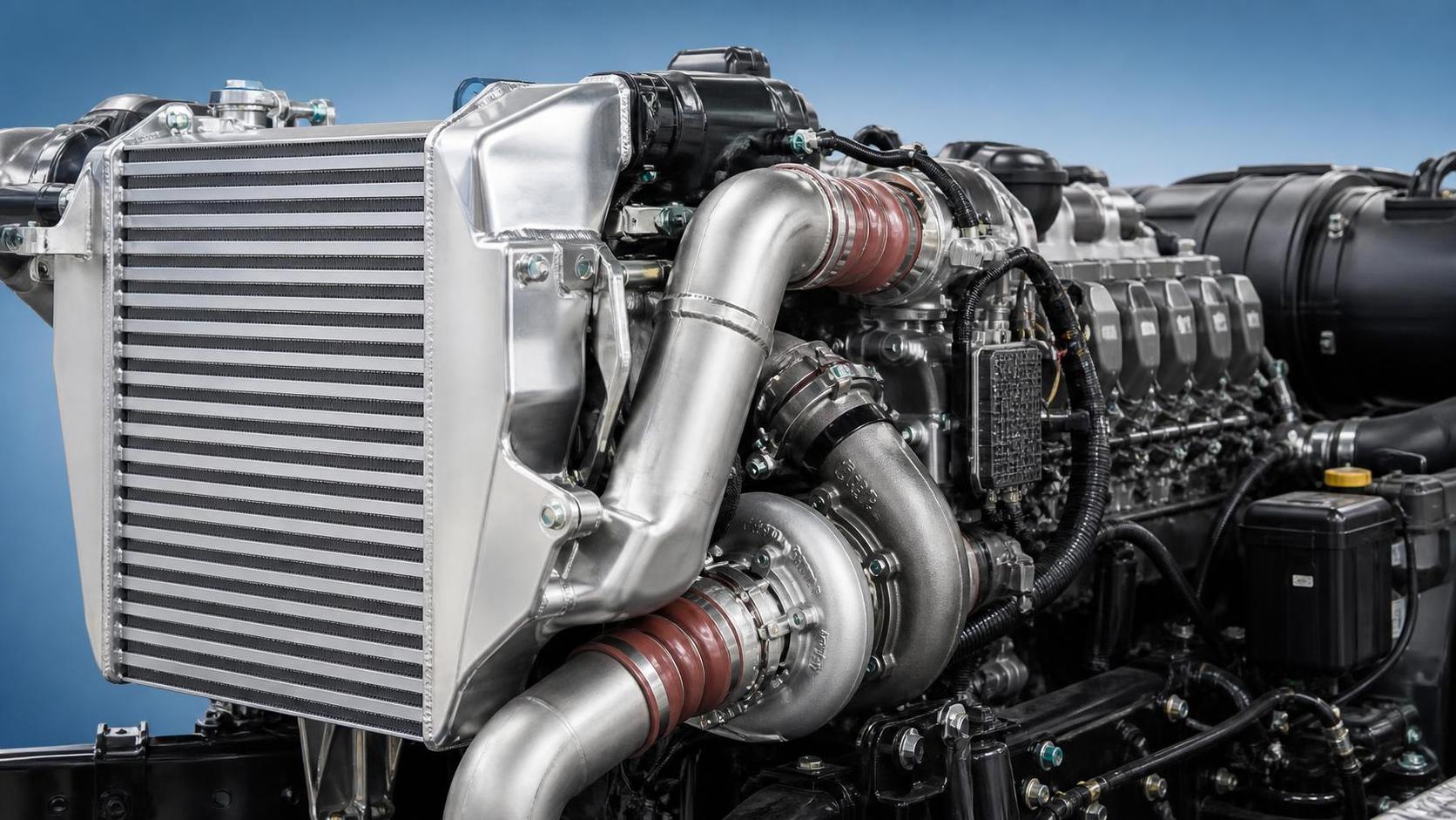
In a boosted engine, an intercooler is expected to do one visible job: reduce the temperature of compressed intake air before it reaches the cylinders. Yet for technical evaluators, the less visible result is often just as important. Every kilopascal lost across the charge-air cooler changes the pressure that actually arrives at the intake manifold, the work demanded from the turbocharger, and the way the engine feels when load changes.
Intercooler pressure drop is therefore not merely a flow-bench figure. In heavy-duty trucks, construction machinery, and other high-load applications, it can influence transient torque, turbocharger operating margin, fuel consumption, exhaust temperature control, and calibration stability. A cooler with excellent heat rejection but excessive restriction may lower charge-air temperature while making the turbo system work harder to deliver the required manifold pressure. Conversely, a very low-restriction core may preserve boost response but leave too much heat in the air charge.
The engineering task is to select an intercooler that manages both sides of the equation under real operating conditions rather than optimizing one laboratory number in isolation.
Pressure at the compressor outlet is not pressure at the engine
Pressure drop is the difference between charge-air pressure at the intercooler inlet and pressure at its outlet. It arises from friction along internal passages, airflow separation at headers, changes in flow direction, fin and tube geometry, abrupt area transitions, and contamination that accumulates in service. If the compressor outlet produces 250 kPa absolute and the downstream intercooler outlet is 235 kPa absolute, the system has lost 15 kPa through the cooler and associated connections.
That loss matters because the engine responds to manifold pressure, not to compressor discharge pressure. To maintain the same cylinder charge, the turbocharger must raise its outlet pressure enough to compensate for the restriction. In steady operation, the control system may achieve this by increasing vane position, wastegate closure, shaft speed, or—depending on architecture—support from an electric compressor. The apparent boost target can still be met, but the cost is higher compressor work.
During a transient event, the effect is more immediate. When a driver requests torque while climbing with a loaded truck or when a hydraulic machine suddenly takes on load, the turbocharger needs time and exhaust energy to accelerate. A restrictive intercooler increases the pressure ratio required at the compressor. This can delay the build-up of usable manifold pressure, especially at low engine speed where turbine energy is limited.
Why a small pressure loss can change boosted engine response
It is tempting to judge restriction only by its absolute value. In practice, the impact depends on the engine’s boost level, compressor map position, mass-flow demand, control strategy, and duty cycle. A given pressure loss may be manageable in an engine with substantial turbocharger reserve, yet significant in an application already operating near its compressor speed, surge, or turbine flow limits.
Three response mechanisms deserve attention.
1. Increased compressor work
To overcome intercooler pressure drop, the compressor must produce a higher discharge pressure for the same intake-manifold target. Higher pressure ratio tends to increase compressor outlet temperature and shaft power demand. This creates an engineering trade-off: the intercooler removes more heat because the air enters hotter, but the turbocharger has generated some of that additional heat in the first place.
At high load, this extra work can move the compressor toward a less favorable efficiency region. The result may be more exhaust backpressure, higher turbine drive requirements, or a narrower thermal margin. The penalty is rarely captured by looking at intercooler restriction alone; it appears in the behavior of the entire air path.
2. Slower pressure recovery after a load step
Charge-air systems contain volume. The compressor, pipes, intercooler tanks, core passages, intake manifold, and connecting hoses form a pressurized system that must be filled whenever boost rises. Restriction between the compressor and manifold limits how quickly pressure propagates downstream. A restrictive core can act like a bottleneck, causing a larger difference between upstream pressure and the pressure available at the cylinders during acceleration.
This does not mean that the intercooler core volume should simply be minimized. Reducing volume too aggressively may compromise heat-transfer area or create excessively high local flow velocity. The useful design target is controlled internal volume combined with smooth, well-distributed flow paths.
3. Reduced usable airflow at high demand
Pressure drop generally rises nonlinearly with mass flow. At moderate engine load, a core may appear acceptable. Under peak torque, high ambient temperature, altitude compensation, or regeneration-related operating conditions, airflow can increase sharply and restriction can become much more consequential. For this reason, a single low-flow test point is insufficient for technical selection. Evaluators should request a pressure-drop curve across the expected air-mass-flow range and assess it at relevant inlet temperatures and pressures.
Cooling performance and restriction must be evaluated together
An intercooler is a heat exchanger, not just an air duct. Its core must transfer heat from compressed air to ambient airflow, coolant, or another cooling medium while maintaining acceptable pressure loss. A larger thermal surface area can improve temperature reduction, but dense fins, narrow passages, and long flow paths can increase resistance. The “best” core is not necessarily the one with the lowest outlet temperature on a static bench test.
A more useful evaluation considers the resulting intake charge density. Density is influenced by both temperature and pressure. Cooling the air increases density; losing pressure decreases it. The balance can be expressed conceptually through the ideal-gas relationship:
Air density is proportional to absolute pressure divided by absolute temperature.
Therefore, an intercooler design should be assessed by the density of air delivered to the engine, not temperature reduction alone. If one design cools slightly better but creates substantially more pressure loss, its net density benefit may be smaller than expected. The correct comparison also includes the additional compressor work required to recover the lost pressure.
For heavy-duty applications, sustained heat soak adds another layer. A core that performs well at the start of a test may behave differently after prolonged climbing, hauling, or high hydraulic demand. The preferred unit maintains stable thermal effectiveness without imposing a restriction that forces the turbo system into an unfavorable operating condition.
Core geometry: where the trade-off is created
Most pressure-drop characteristics are established long before the cooler reaches the vehicle. They originate in core architecture, tank design, manufacturing consistency, and installation geometry.
- Tube or passage dimensions: Smaller hydraulic diameters can intensify heat transfer by increasing surface contact and turbulence, but they also raise frictional losses. Passage shape affects both velocity distribution and boundary-layer behavior.
- Flow length: Longer internal paths provide more heat-transfer opportunity but generally increase pressure loss. The ideal length depends on available frontal area, cooling-air velocity, and required duty point.
- Fin configuration: Internal turbulator patterns promote heat transfer, yet overly aggressive designs may create unnecessary restriction. External fin density must also be balanced against dust tolerance and airflow through the cooling stack.
- Header and tank design: Even a well-designed core can underperform if inlet and outlet tanks distribute air unevenly. Poor distribution creates localized high velocity, dead zones, and inconsistent thermal loading across the core.
- Port transitions and piping: Sharp hose steps, undersized connectors, tight-radius bends, and misaligned joints can add meaningful loss outside the core itself. System pressure drop should include the installed assembly, not only the bare intercooler.
For evaluators comparing replacement parts, dimensional compatibility alone is not enough. Mounting location, connection diameter, tank orientation, and apparent core thickness do not reveal internal flow design. A part may fit physically while altering the boost system’s pressure-loss profile and thermal behavior.
How to interpret pressure-drop data without being misled
A published pressure-drop figure is valuable only when its test conditions are understood. Ask whether the value was measured with dry air, at what mass flow, at what inlet pressure and temperature, and whether the measurement includes tanks, ports, or connecting pipes. Results reported in different units should be normalized carefully: kPa, mbar, psi, and inches of water are not interchangeable without conversion.
More importantly, distinguish between a component test and an installed-system result. A clean laboratory core may show modest restriction, while the vehicle installation adds pressure loss through hoses, clamps, resonators, sensors, elbows, and packaging-driven transitions. In off-road machinery, dust, oil mist, and external debris can further change both air-side and charge-side performance over time.
A robust technical review usually includes the following questions:
- What is the maximum expected charge-air mass flow at rated power and transient torque demand?
- What manifold pressure must be achieved, and what compressor discharge pressure is available with acceptable turbo speed margin?
- What pressure-drop limit is appropriate at nominal and peak flow?
- How does outlet temperature change at the same operating points?
- Does the design maintain acceptable flow distribution after installation in the actual cooling package?
- What happens as fouling, vibration, thermal cycling, and hose aging enter the service picture?
These questions move the discussion away from an isolated “low pressure drop” claim and toward a defensible system decision.
Transient response is not solely an intercooler problem
When boost response is poor, the intercooler can be a contributor, but it should not become the default diagnosis. Restricted air filters, leaking charge-air hoses, cracked tanks, loose clamps, turbine-side limitations, EGR behavior, variable-geometry actuator faults, intake-throttle operation, and calibration constraints can produce similar symptoms. A measured pressure differential across the cooler is more informative than visual inspection alone.
For a field check, pressure sensors should be placed as close as practical to the intercooler inlet and outlet, with readings recorded through a controlled load sweep. Comparing actual differential pressure against the expected curve can reveal whether the issue is core restriction, a downstream blockage, or a broader turbocharging problem. Temperature readings on both sides of the cooler should be captured at the same time, because a core with low restriction but insufficient cooling may also undermine torque consistency under heat load.
Leak testing remains essential. A leak does not create the same restriction signature as a blocked core, but it can force the turbocharger to work harder and make response feel similarly weak. The diagnostic goal is to separate pressure loss from pressure escape.
Application considerations for trucks and construction equipment
Heavy trucks often spend long periods near high torque, where sustained thermal performance and moderate restriction are both necessary. Construction equipment faces a different but equally demanding profile: abrupt load changes, variable engine speeds, high dust exposure, compact cooling packages, and sometimes low vehicle speed that limits ram-air flow. In these settings, external fin blockage can degrade cooling while internal contamination or oil carryover can alter charge-side flow.
The cooling stack also matters. A charge-air cooler positioned alongside a radiator, oil cooler, condenser, or battery thermal module operates within a shared airflow environment. Improving one exchanger’s fin density may reduce airflow available to another. Technical selection must account for the complete module rather than treating the intercooler as an isolated component.
Liaocheng Xinde Auto Parts Co., Ltd. develops radiators, intercoolers, construction-machinery radiators, and related thermal-management components for heavy trucks and new-energy applications. For replacement and platform-evaluation work, the practical value of this manufacturing focus lies in examining the full combination of core construction, tank geometry, sealing integrity, and integration within the cooling package—not simply matching external dimensions.
When reviewing a vehicle-specific option such as MERCEDES-BENZ, evaluators should confirm the intended engine variant, charge-air routing, sensor provisions, mounting arrangement, and required airflow range. Similar vehicle families may use different boost targets and cooling-pack layouts, making visual interchangeability an unreliable selection method.
A practical acceptance framework
Before approving an intercooler design, establish a target window rather than chasing one extreme. Define the allowable pressure-drop curve, required outlet-temperature performance, burst and fatigue expectations, airflow-distribution criteria, and installation constraints. Then validate the unit at representative engine operating points, including high-flow conditions and heat-soak exposure.
Particular attention should be paid to repeatability. Variation in tube brazing, fin formation, tank welding, internal cleanliness, or port geometry can cause production parts to deviate from prototype performance. A technically sound specification should therefore include inspection and validation methods, not only nominal dimensions.
The most successful intercooler design is often unremarkable in use: the engine reaches requested torque without hesitation, intake temperatures remain controlled, and the turbocharger does not need to operate at the edge of its map merely to overcome air-path losses. Achieving that result requires treating pressure drop as a system-level variable. It is the balance between airflow freedom, heat rejection, structural durability, and real installation conditions that ultimately determines how a boosted engine responds.